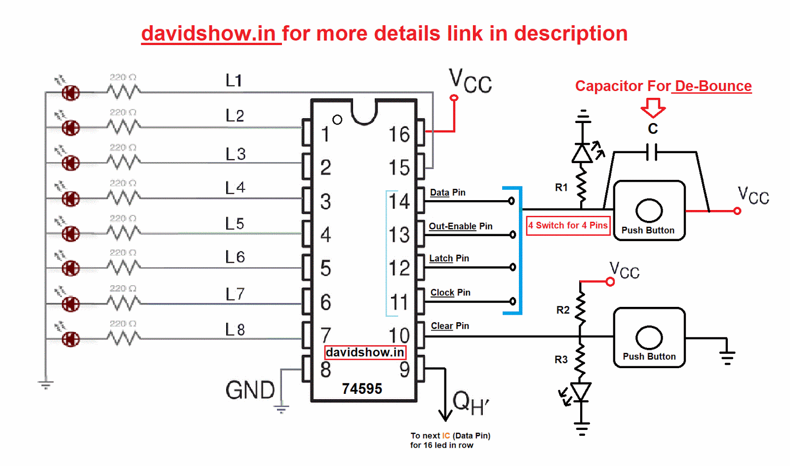
Universal Shift Register Circuit Diagram

Emmanuel Larson

Using circuit shift register right flip state flops schematic multiplexers redesign figure four clock simulate circuitlab created Shift registers with circuit diagram Shift universal register bit circuit logic explain diagram operation

(Solved) - Redesign the right-shift register circuit of Figure 12-10

(Solved) - Redesign the right-shift register circuit of Figure 12-10

Explain the operation of 4-bit universal shift register. F-alpha.net: experiment 18 Shift registers with circuit diagram

Register shift circuit schematic working why installed simulating buttons actual push currently button note side don

Shift registers latchRegister shift bit diagram flip flop circuit experiment alpha electronics .

.

(Solved) - Redesign the right-shift register circuit of Figure 12-10

f-alpha.net: Experiment 18 - Shift Register

Shift Registers with circuit diagram

PPT - 4-Bit Universal Shift Register PowerPoint Presentation, free

Shift Registers with circuit diagram

arduino - Why is my shift register circuit not working? - Electrical

Explain the Operation of 4-bit universal shift register.


YOU MIGHT ALSO LIKE