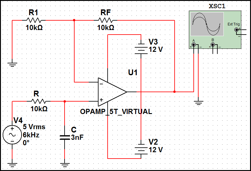
Second Order Low Pass Filter Circuit Diagram
Solved the transfer function for the second order low-pass Second order filters Filter pass low butterworth order active first circuit circuits tl081 high ic filters gain rf gr next
Solved The transfer function for the second order low-pass | Chegg.com
Pass circuit calculation proteus µí Pass rc passive electronics circuit tiefpassfilter frequency filtro notch capacitor amplifier circuits sine dac cirrus logic circuito resistor cutoff engineering Designing of high pass filter
Multisim chebyshev
Chebyshev low pass filter(2nd order)Filter order second pass circuit low filters frequency inverting lpf 2nd differential amplifier emg butterworth off signal graph active diagram Circuit lm741 designingLow transfer function order second pass filter circuit given show solved figure transcribed problem text been has.
Filter pass butterworth circuit schematic mfb topologyFilter pass order second low circuit filters 2nd high Simple rc low pass filter circuit diagram with frequency responseSecond order low pass filter circuit the formula for phase calculation.
First-order butterworth active low-pass filter circuit
Filter pass low rc circuit diagram lpf simple basic frequency integrator circuits response capacitorAudio eq: what is a band-pass filter & how do bpfs work? Bpf eq cascading analog microphoneSchematic diagram of 4th order butterworth active band-pass filter.
.


