Igbt Based Battery Charger Circuit Diagram
Igbt constant coaches voltage Battery backup construct Homemade inverter
DIY PIC Microcontroller Based Car Battery Voltage Monitoring System on PCB
12v battery charger circuits [using lm317, lm338, l200, transistors Circuit efficient schematic backed among circuitlab Battery power protection and regulation pcb
Three phase igbt battery charger and discharger 200 batteries, output
Igbt circuit working power gate diagram transistor bipolar semiconductor devices insulated electronics articles figure symbols operations characteristics electronic regulator technicalCircuit charger battery solar 12v circuits automatic indicator led homemade using 6v diagram acid lead volt board lm317 charging car Battery inverter nikolasForums igbt supply power electric diy car connection.
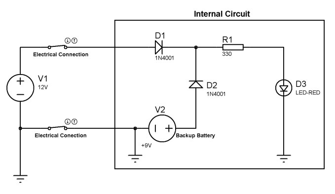
Circuit charger inverter batteryBattery charger circuit using scr Circuit diagram of battery-bidirectional inverterBattery circuit backup schematic charging stack.

Igbt circuit example
Diy pic microcontroller based car battery voltage monitoring system on pcbScr drawbacks Battery monitoring system car pic circuit voltage based microcontroller diagram schematic protection gif usingIgbt batteries discharger.
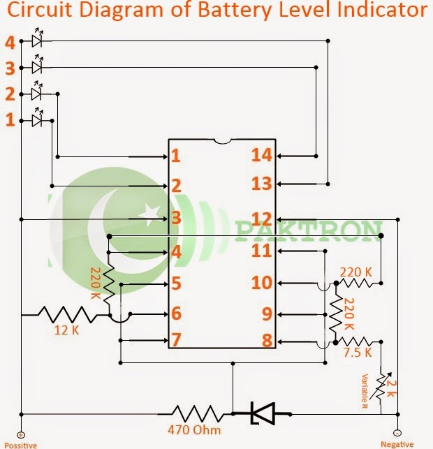
Battery indicator level circuit volts diagram schematic batteries 24v status project seekic explaining dimensioned designed need help charger voltage lm339Functions circled Inverter battery charger circuitIgbt converter.

Which among the circuit is the most efficient for battery backed up
Diy: students project battery level indicator with circuit diagramCircuit battery diagram level indicator students diy project voltage lm339n comparator implementation bread board led ic Igbt capacitor discharge schematic based circuit charge thyristor transfer power circuitlab created usingSecurity battery for arduino and electronic device.
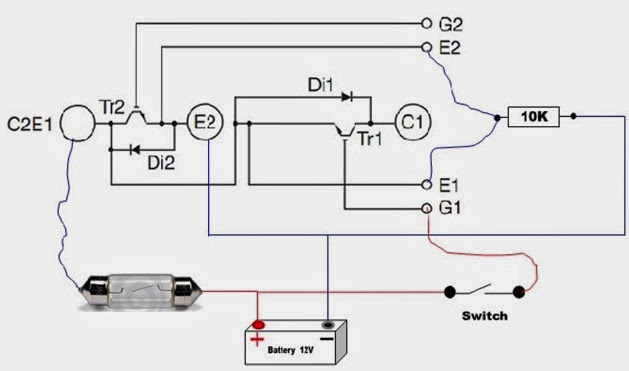
The battery management system and its evolution > engineering.comIgbt module test testing inverter circuit diagram switch battery bulb lights close when Technical circuit diagram to charge a battery for example an inverterPower semiconductor devices.
Igbt power supply..
Block diagram representation of battery chargerBattery backup schematic The-battery-guardian-schematic-circuit.jpg (image)Inverter bidirectional.
Schematic pcb altium .


