Control Valve Schematic Diagram
3 minutes to know common control valves works Valve control basic principles principle majority valves oversized actuators however undersized attributed probably problems Schematic diagram of a control valve.
An example schematic drawing I created to show some standard symbols
Control valve parts valves instrumentation Directional valves schema gate Basic parts of control valves
What is thermostatic expansion valve? working, construction
Control valve positioner circuit diagramControl valve Continuously-controlled valve schematic.Control valve.
Valve control principle actuators system pipeValves actuator positioner instrumentation functions instrumentationtools principle breather understanding boiler Chapter 19: control of actuators for process valvesHydraulic flow control valves.

Scheme of control valve
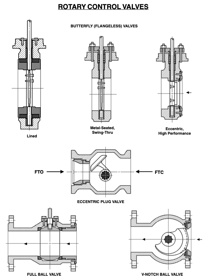
Valve control actuator pneumatic diagram schematic air fisher citizendium milton pd main pressureValve rotary glossary Valve valvesControl valve basics.
Scheme of principal parts of a control valve. taken from [2Control valve glossary Thermostatic electricalworkbook evaporatorBasic control valve principles – paktechpoint.

Control valve
Control process valves actuators valve schematic pneumatic system figureValves instrumentationtools Control valveSchematic drawing valve example diagram control electrical symbols created standard show some simplified figure.
China industrial control valves manufacturer & supplierAn example schematic drawing i created to show some standard symbols Flow control valve hydraulic diagram pressure compensated parker operation valves dcv 31b permission hannifin reprinted showing figure corpContinuously controlled.

Steering corvette rebuild
.
.


