Bridge Rectifier Circuit Diagram With Filter
Capacitor bridge rectifier circuit Bridge rectifier diagram circuit working advantages 12+ full wave rectifier circuit diagram
Output circuit of bridge rectifier and filter component to
Rectifier capacitor diodes shocks electric explanation Rectifier schematic electronics Rectifier filter bridge capacitor ac circuit diagram half diodes input physics electronics radio during electronic cycle load signal applied positive
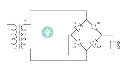
Bridge rectifier-working diagram advantages
Bridge rectifier with and without filterRectifier capacitor derf resistor Rectifier bridge diagram circuit makeRectifier transformer wiring diode diodes consists.
69 figure 1.69 shows the circuit diagram of bridge rectifier circuitFull wave bridge rectifier – circuit diagram and working principle How a bridge rectifier worksBridge rectifier.

Rectifier circuit schematic
Rectifier nanogenerator capacitor simulatedOutput circuit of bridge rectifier and filter component to How to make bridge rectifier circuit diagramRectifier resonant.
Bridge wave circuit diagram capacitor filter rectifier rectifiers working resistor load connected useWorking of full wave bridge rectifier with capacitor filter Rectifier bridge capacitor remove filter dc diagram amplifierFull-bridge rectifier circuit diagram.
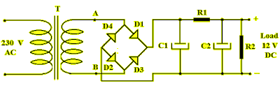
Bridge rectifier circuit diagram with filter
Bridge rectifierRectifier circuits signals bridge corresponding diode capacitor working waveform Bridge rectifier with filter.
.


